A Solid(s) Optimization Game
It can be crucial for a structural element in a design to perform its purpose while occupying the least amount of space and mass. As a result, the total design is lightweight while maintaining its desired strength.
A given block of acrylic is required to be machined into a shape that would produce the highest strength-to-weight ratio achievable. The failure load also needs to be predicted. It will undergo a tensile test to ensure that the design is sound.
For our purposes, we define “strength” as the force (N) required to cause failure due to tensile stress and “weight” as the mass (g) of the design.
What are we given?
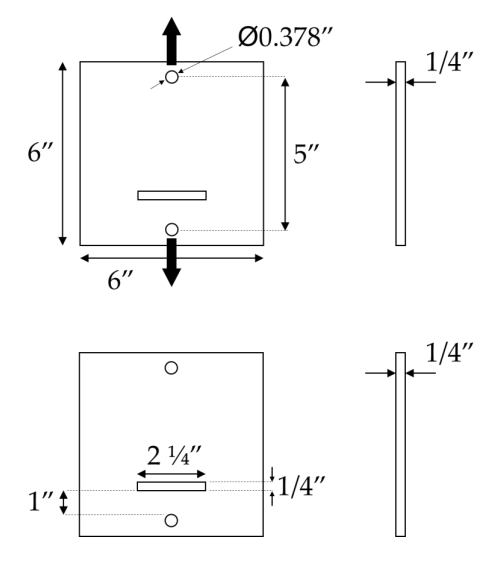
Current Design and Dimensions of Acrylic PMMA
An Acrylic PMMA was provided with a slot and two holes at the top and bottom as shown clearly in the image with the dimensions.
Here are a few important design constraints:
The acrylic plates are 0.25” thick and cannot be changed.
The pins on while tensile forces will be exerted upon have a 0.375” diameter and need at least a 0.378” clearance hole.
The minimum distance between the pins must be 5”.
The slot in the middle of the plate shows where there cannot be any material but the slot can be increased if desired.
The 1” distance shown is between the bottom of the slot and the top edge of the pinhole.
Holes and cutouts in the acrylic should have a diameter of at least 3 mm.
The acrylic has the following properties:
(a) Density: 1188 kg/m^3
(b) Tensile Ultimate Strength: 70 MPa
(c) Compressive Ultimate Strength: 120 MPa
How will we approach this?
The method by which the current design for acrylic will be redesigned to give maximum strength-to-weight ratio is as follows:
Current Design Analysis and Framework
Slot Geometry Optimization
Exterior Shape Optimization
Weight Optimization
By the end of this, a final design will be proposed and ready for tensile testing.
Design Approach -
Design Approach -
1. Current Design Analysis and Framework
An FEA Analysis was done on the current design to see at which force it fails and what the strength-to-weight ratio is. This will be our comparison framework for upcoming stages. The important outcomes from the FEA Analysis were as follows:
Force at Failure: 1930 N
Mass: 171.38 g
Strength-to-Weight Ratio: 11.26 N/g
Location of Failure: Top Hole
A 3D analysis was done in ANSYS, using a bearing load in the Z direction at the top hole representing the load that would be applied through a pin. Additionally, cylindrical support at the bottom hole mimics how the part would be supported at the other end with another pin. Meshing is done at a size of 3 mm over the majority of the part with a refinement of 3 (i.e., 1 mm) at all critical features, in which critical features are selected using the face tool to account for the 3D model. This mesh refinement combination represents a fine edge between the maximum number of elements our simulation program can handle, while also maintaining a reasonable computational time for force iterations. All simulations will follow this methodology.
Current Design with Strength-to-Weight ratio 11.26 N/g
2. Slot Geometry Optimization
If the slot width is increased, the maximum stress would be higher since the net area would be smaller. Thus, the slot cannot be increased, however, it can be rounded off on the sides by appropriate radii. This rounded effect is for reducing stress concentrations around it.
Two cases were done: A 0.0625” radii on both sides of the slot were tried out, and then radii of 0.125” on both sides. The results indicate that safety factors increased around the edge in the current design from 1.19 to 1.73 and 2.29.
Radii 0.0625” giving safety factor of 1.734
Radii 0.125” giving safety factor of 2.291
3. Exterior Shape Optimization
The design proceeding forward with is the one with the radii 0.125”. On this, the stress fields were mapped for 2 cases: tension & compression.
Stress Map for Tension
Stress Map for Compression
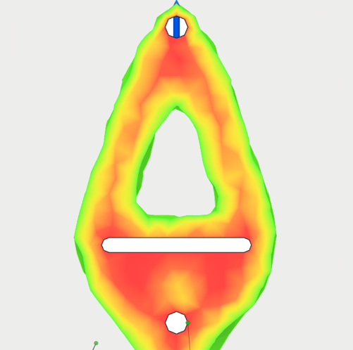
To maximize our strength-to-weight ratio we should create a geometry that encompasses as many of the critical stress regions outlined in the compressive and tensile simulations from the original part as possible. But, more particularly, should prioritize the stress map for tension, considering the fact that the part will fail primarily in tension. From this, we can see that to capture these regions the part will have an egg-like shape being more elongated near the side of the slot and less near the top.
Using topology optimization, we can best capture these regions, and use this to get a good initial approximation of an ideal outer shape which resulted in an approximate 30% mass reduction compared to the original design. For the first iteration, a conservative amount of material is used in critical regions. A triangular shape cutout is used in the center being parallel with the outside geometry to create a constant cross-sectional area on both sides of the feature as shown.
Topology Optimization Reducing 30% Mass
Refined Design from Topology
FEA Analysis on Refined Design
Under loading conditions of 1930 N, we can see this first design will primarily be at the top hole, similar to the original with a safety factor of 0.821 (18% reduction). This means that too much material was removed beside the top hole, thus weakening it. We can also identify that the slot feature would be the second point of failure having a minimum safety factor of 1.20. Also, areas depicted in blue around the triangular cutout as well as below the slot still experience minimal stress with extremely high safety factors. Thus, we can iterate to further remove material from such regions.
4. Weight Optimization
Combining the slot and triangular hole geometry, we optimized the following designs:
A - Mass: 42.06 g, Thickness: 1.5 cm ; B - Mass: 37.85 g, Thickness: 1.0 cm ; C - Mass: 35.33 g, Thickness: 0.7 cm
The Design C was proceeded with, thus now optimization is on the area around the hole and below the slot, which led to the following designs:
D- Mass: 27.00 g, Thickness: 0.7 cm ; E- Mass: 32.47 g, Thickness: 0.7 cm ; F- Mass: 31.73 g, Thickness: 0.7 cm
The Design F was proceeded forward with with minor changes to form the final design ready for tensile testing.
Final Design -
Final Design -
Design F was used with slight interior/exterior dimensional adjustments to create a final design as shown.
The important outcomes from the FEA Analysis yielded:
Force at Failure: 1900 N
Mass: 28.44 g
Strength-to-Weight Ratio: 66.81 N/g
Location of Failure: Top Hole
Thus, this represents nearly 6 times the strength-to-weight ratio as the current original design provided while supporting nearly the same force at failure.
Final Design with Strength-to-Weight ratio 66.81 N/g
However, it is to be noted that once the design was complete and machined for testing, the tensile test yielded a force at failure less than 1900 N as predicted for the design. It failed at 12% lower than the estimation at 1672 N. This happened considering the post-machining effects, that led to micro-cracks being introduced. A crack length of 125 μm was calculated to cause rupture for an approximate strength of 70 MPa.


