
A 3-Axis Auto Tool Changing CNC Mill Kit for Hobbyists
Engineering design students and manufacturing hobbyists all face one problem when it comes to manufacturing their designs or hobby projects as intended.
Students are typically low on budget and tend to rely more on 3D printing to create prototypes, but those are not fully functional at scale. Hobbyists take the extra step to get themselves CNC Routers (spindle movement in x, y, and z), but they only machine relatively soft and flat materials. On the other hand, it would be a dream for all to purchase a CNC Mill (spindle movement in z, table movement in x and y) that potentially machines hard metals into many shapes with high accuracy, but it is highly expensive and mostly found in an industrial setup.
Wouldn’t it be nice to build a CNC Mill that can machine not only hard but a wide range of materials, come in a kit design so anyone can use their IKEA skills to make it and fit in their design workspace, and yet be affordable to the target user? That is exactly what has been designed.
Engineering Specifications -
Engineering Specifications -

FUNCTIONS & INPUT-OUTPUT


OBJECTIVES

CONSTRAINTS

DESIGN STANDARDS

Final Design -
Final Design -
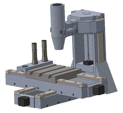
The conceptual designs drafted prior to selecting the final design were based on higher priority objectives like affordability, machinability of a range of materials & operational efficiency. It is to be noted that all conceptual designs had a few design features that were consistent: the motors for the power source, lead screw actuator design for X, Y, and Z motion, and cartridge spindle design. After a comparison analysis of all CNC designs, the final design chosen was a 3-Axis CNC Mill with Autonomous Tool Changing System.


Design Working Principle
The design mechanism enables the autonomous changing of up to 3 distinct tool bits that are clamped within standard R8 collets.
The general principle for how the autonomous tool-changing system should operate is explained below:
The operator will load their desired tool set, by placing one directly into the spindle and the other two into the tool magazine, and will indicate which sized bit is in which corresponding slot.
The spindle will machine a material using the first cutting tool held in the collet.
When a different tool bit is required the table will move in the necessary X and Y directions to align the empty slot in the tool holder with the spindle.
The spindle will move downwards in the Z direction and release the tool with its collet into the corresponding slot using the end effector mechanism.
The Y position of the table will then move to align the spindle with the next tool bit, and the Z axis will move downwards until the collet is fully engaged inside the spindle.
When the mandrel and collet thread make contact, the end effector will clamp onto the collet and the motor will rotate the mandrel mating the threads.
In order to enable this process two mechanisms are needed the first being a device to lock the rotation of the spindle (Robotic End Effector), and the second to support and hold the collets that are not in use (Magnetic Collet Holder).
A. Robotic End Effector
In order to be able to automatically and reliably exchange collets, it was determined a new mechanism would need to be incorporated to loosen and tighten the thread mates between the mandrel and collet. To do so, this device must be able to autonomously clamp onto the collet and lock its rotation. The use of a robotic end effector with two arms, situated in opposing slots on the spindle, can engage and provide the necessary radial force to lock the collet.

Robot end effector mechanism and its parts
B. Magnetic Collet Holder
After several iterations, it was determined that the simplest and most cost-effective mechanism was to place the tool magazine on the side of the table. As it is situated in the X direction, the range of motion in this axis was extended to ensure a range of 25 cm was still achieved.
The tool magazine is composed of an aluminum plate of dimensions 5cm x 20cm x 3cm with three 0.750” holes to allow clearance for both large and small tool bits. The holes are positioned 8.5 cm apart, with consideration of the diameter of the spindle, enabling it to engage with the selected collet without interfering with those beside it.

X and Y axis move to position spindle above the collet - spindle will then move downwards in the Z axis until the collet is fully contained within it
Through the designing process, it was determined that traditional clamping methods, which interfere with the spindle’s ability to fully engage up to the front face of the collet, would require an additional mechanism to further pull the collet upwards. To avoid this the clamping mechanism must only be applied axially, and not radially, to the front face of the collet.
To address this issue magnetic strips are placed around the edges of the circular holes and are attracted to the edges of the collet face. This being in combination with the chamfer on the front end of the R8 collets, slightly sinking into the holes, ensures the collets are able to be kept both upright and stationary.

Tool holder supporting two collets
Design Parts & Material Selection
The other components in the design are the Column, Ram, Table, Actuator Mechanism, and Spindle Motor.
Column
The function of the column is to support the ram which will, in turn, support the spindle. In this case of designing a bed-type mill, the spindle only moves in the Z-direction being enabled by the column. The column will feature a lead screw mechanism that drives the ram and spindle vertically and is guided by dovetails rails along the outside of the column. The column also contains a mounting plate that allows for the motor to be secured in place. Additionally, triangular supports are attached to the sides for increased rigidity, which also lowers the center of mass improving stability and vibration damping capabilities.
The chosen material for the column is 6061 aluminum alloy, which has high strength but is also very light. The column is one of the larger components of the design and therefore would be extremely heavy if it were made out of a harder and heavier metal like steel.
The column is manufactured out of individual plates, allowing it to be contained within a kit and also making it easier to manufacture, further decreasing the cost. The individual parts will be screwed on using 0.25 & 0.5” - 20UNC bolts. The column will then be directly bolted onto the Y-axis actuator support.

Exploded view of the column
Ram
The ram is a custom part that provides support for the spindle and will be manufactured from a single piece. The circular hole it contains near the back is threaded to allow for rotation of the lead screw and motion in the z-axis. The rectangular holes machined onto the ram are used to contain and support the end effector mechanism. The ram also contains dovetail slots to the sides which lock onto the dovetail rails on the column to allow for sliding on the Z axis.

Design of the ram
Table
The table used in this design has dimensions of 20 cm x 26.3 cm x 3 cm. It is a standard T-slot plate that allows for the use of many different types as well as combinations of mounting tools. The corresponding T-block and fastener are used to directly attach vices, angled mounts, fixturing squares, toe clamps and much more. It is extremely versatile being adaptable for fixturing in terms of both required positions and angles. It can also accommodate the mounting of distinct shapes including cylinders through the use of a rotary clamp. Due to being subject to heavy wear and to suffice for longer-term use, it is made of Cast Iron. These T-slot plates are highly standard components and can be found amongst a large set of suppliers in a variety of sizes and materials. To enable the movement of the table a lead screw nut is attached to the bottom, and dovetail slots are cut on either side.

Design of the table
Actuator Mechanism
Two lead screw actuator mechanisms were chosen to move the table in X and Y directions after considering a number of alternatives. These lead screw actuators are stacked on top of each other using dovetail rails, which allow efficient sliding. Each actuator was broken into 7 components, and their assembly for the kit manual has been highlighted.
The design for the actuator was based on initial measurements before the assembly was optimized for greater efficiency. This ensured that there was a sufficient factor of safety involved.
The main design considerations while designing the lead screw actuators were ensuring table movement, preventing back drive and eliminating backlash.

Exploded view of the X Axis Actuator Support

Exploded view of the X Axis Actuator

Exploded view of the Y Axis Actuator Support

Exploded view of the Y Axis Actuator
For design interest, the assembly steps for each actuator have been outlined in 8 steps below:
Install side walls
Assemble the anti-backlash nut:
(a) Insert the lead screw through the bore in the half-spool
(b) Screw the rim of the spool to one face of the lower projection of the X actuator (table in the top actuator’s assembly).
(c) Fix the spring flush against the face of the projection on the opposite side of the screwed rim, wound around the inner cylinder of the spool
(d) Press fit the second rim onto the spool from the spring’s side, such that the spring is pressed between the second rim and the table, but is neither compressed nor extended.
Now insert one end of the lead screw into the beam coupling, and then fit the beam coupling inside the front wall.
Fit the motor into the slot provided on the opposite face of the front wall. The shaft should fit inside the coupling automatically.
Screw the motor to the front wall and the front wall to the side face of the central base in the holes provided.
Screw the back wall to the opposite side face of the central base.
Press-fit the roller bearing at the free end of the screw.
Press-fit the back wall onto the bearing. The screw will not directly touch the wall, by virtue of its length.
NOTE: The motor used in this design was the NEMA 34 Stepper Motor (50-ounce-inch operational torque and 1.8° step size).
Spindle Motor
The main factor taken into consideration when selecting the spindle motor was the type of material to be machined. From the objectives section, the maximum Rockwell B hardness value that will be worked with is 88, which makes Steel 304 the hardest material that our machine will have to mill. With this knowledge, it was determined that the maximum rpm required for the machine was around 5300 rpm.
The two most common types of motors used in CNC mills are stepper and servo motors. Due to the servo’s ability to maintain its torque at high speed, this was the choice for the spindle motor, as cutting harder materials and using a larger tool diameter demands higher torque. The torque remains relatively constant at 1.3 Nm for Servo Tpk. From this, the Power of the spindle was found to be 721 W, ie. 0.96 hp.
While the stepper is generally cheaper, its maximum rpm along with the torque capability tends to be much lower than that of the servo, which would not allow our mill to machine harder materials such as Steel 304.
Limitations of Design
We shall compare our design to a standard 3-axis CNC Mill & 5-axis CNC Mill to see where our design lies in terms of operational efficiency and the feasibility to create arched and sloped cuts.
Operational Efficiency
Let’s assume we have a reference part as shown that needs to be machined. The description of the part is as follows:
There is a cube with dimensions of 6 cm x 6 cm x 6 cm
It has 2 holes on each side of its face except only 1 side. This means 5 sides of the cube have holes and 1 side has none
The 2 holes are of different diameters: 1 cm and 0.5 cm
The holes are 3 cm apart
The depth of each cut is 0.75 cm
Standard 3-axis Mill: It will mill five 1 cm diameter holes in five separate operations. It will then mill five 0.5 cm diameter holes in five separate operations. In total, to mill the desired shape, it will require 10 operations.
Standard 5-axis Mill: It will mill five 1 cm diameter holes in a single operation due to access to all five sides of a cube at one go (rotation of table in 5 axis). Then, it will mill five 0.5 cm diameter holes in one more operation. In total, to mill the desired shape, it will require 2 operations.
3-axis Mill with Automatic Tool Changing: It will mill one 1 cm diameter hole of a face and change tools and mill one 0.5 cm diameter hole of the same face. This is a single operation. Then same process repeats for 4 other sides. In total, to mill the desired shape, it will require 5 operations.

Reference Part for Operational Efficiency
Arched and Sloped Cuts
Now, let’s assume we have a part with a downward slope in the middle, bounded by two plates that have chamfers and radii on them as shown. The downward slope indicates an angled cut to be made by a milling machine.
Standard 5 Axis Mill:
The 5-axis mill design can create both angled and arched cuts since it contains two extra axes for the table to rotate and tilt. This can be achieved with the part sitting flat on the table. The design can also create the chamfer without the need for a chamfering tool.
Standard 3 Axis Mill and 3 Axis Mill with Automatic Tool Changing:
Both of these designs cannot create angled or arched cuts with the part sitting horizontally on the table since there are only 3 axes of movement. However, only angled cuts can be done, by clamping the part in an angled position, and then worked on in the typical fashion. Arched cuts (radii) cannot be achieved with either design. As for the chamfer, a chamfering tool must be used.

Reference Part for Arched and Sloped Cuts
Conclusion -
Conclusion -
Let’s see how well our design has met the objectives.
1. Achieve dimensional accuracy with cuts: Succeeds with accuracy +/- 0.005”
2. Maximize feasibility of creating angled cuts: Can cut at angles; can chamfer with a chamfering tool; cannot do arched cuts
3. Maximize ease of manufacturing: Every component in design is a standardized part other than the robotic end effector, magnetic tool holder, ram design & the holed spindle to allow clearance for the robotic end effector
4. Possess the ability to machine a large range of material types: Succeeds with machining materials of Rockwell B value of maximum 88
5. Be affordable, in contrast to designs with similar functions: Succeeds with a price range of around $2500-$3000
6. Maximize operational efficiency: Succeeds by taking a much lower number of steps than a standard 3-axis CNC mill, but a slightly higher number of steps than a standard 5-axis CNC mill
Since our main priority objectives were the last three (Objectives# 4, 5, 6) and the design succeeded in it along with other criteria, it is now ready for the next steps. The next steps for the project will involve manufacturing the components and assembling the final design before launching it in the market. Question is…how will I manufacture it? 😉