A Patio Umbrella Designed for Elderly Accessibility
The patio umbrellas currently on the market have the drawback of requiring the user to stand upright in order to fully raise the "slider" and open the umbrella. Additionally, the user must have strong shoulders and enough range of motion to push the runner all the way to the top and then hand crank. These are two qualities that the majority of users, the elderly, frequently lack because many of them may be in wheelchairs and their muscles have atrophied. A typical patio umbrella can also be hazardous since it puts older people in vulnerable positions where they risk hurting themselves or falling while attempting to open the umbrella.
The patio umbrella's current design has to be modified so that it may be raised to its maximum height with fewer crank turns, with less input force, and with a deployment time that is less than or comparable to the current design, subject to the requirement that the umbrella's dimensions remain unchanged.
The trajectory and path of the current design and the final proposed design should be compared to ensure the proper functionality of the design.
Current patio umbrella dimensions to remain unchanged in final design
Labelled components in the current patio umbrella design
Current Design Working Principle:
The current design supports an umbrella canopy from a beam supported at one end, i.e. a boom, (5), connected to the ground (1) through the mounting pole (2). It is comprised of two main mechanisms:
Canopy Deployment Mechanism
When a cable tied to runners (7/9) under each rib or boom (5/6) is pulled, the canopy opens. A control module is positioned on the canopy positioning slider (4), and the cable is fed through the hub (8) and then through an internal pulley system (5). Turning the actuator crank on the slider (4) manually retracts the cable. Closing the canopy requires reverse cranking.
Canopy Positioning Mechanism
The mounting pole's (2) height and angle in relation to the boom (5) decide the canopy’s position. The height of the canopy is controlled by a 2nd actuation mechanism on the slider (4), which must be disengaged to manually slide. The two cantilever arms (3 & 5) attached to the mounting pole (2) together create a triangle linkage, which is used to control canopy tilt in a manner similar to dis-towing. The canopy is aligned horizontally with the ground by manually sliding the slider (4) higher to shorten the distance between the strut (3) and boom (5). This also reduces the angle between them. To increase the tilt, the opposite is done.
Demonstration of Current Design:
Person standing upright using his arms to push the runner upwards and hand crank to open the canopy
Final Proposed Design
-
Final Proposed Design -
The current design requires two different inputs to operate: slider and hand crank; and employs numerous moving parts to achieve complex trace paths/motions.
However, constraining the full operation of the umbrella with a single input would amalgamate multiple motions given the right trace path, drastically reducing both operation effort and time. Thus, simplifying the cantilever linkage and canopy was the first major design choice, which trimmed the number of major components from over 20 to under 10.
Final Proposed Design Mechanism Sketch
The current design’s triangular linkage was inverted such that the cantilever boom (5) now pivots from where the strut (3) used to be. Instead of a slider, this design employs a sliding rack (4) and fixed pinion-crank mechanism (7) such that height control may be actuated from a fixed lower location. The canopy itself consists of 2 hinged rectangular frames (6) mounted on the strut (3) and boom (5). Manual lifting of the slider is now supplemented with a stationary crank at the base (7), which translates rotation through a belt drive to the pinion and rack. Turning the crank lifts the rack and the strut, while the reverse lowers them. It may be fixed at any location using similar braking clamp systems as the current design, which was dismissed from the scope of analysis.
Click to see the entire design: CAD Link.
Final Proposed Design Working Animation
Final Proposed Design Close Up View
Discussing Results
1. Minimizing Operation/Deployment Time
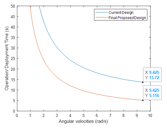
Current Design: The position of the hand crank is located on the slider. Users have to raise the slider to the maximum height and then hand-crank to open the canopy. This involves 2 steps. From several user data, it has been seen that it takes roughly 6 seconds to push the slider up to the desirable max height. After that, the time taken for the opening of the canopy through the hand crank is achieved by the relationship: t=72.76/ω, where ω is the angular velocity. This relationship was found by analyzing the length of the cord that needed to be retracted from closed to open position, which was 3.03 ft (0.924 m). With a hand crank spool of 1-inch diameter, the relationship was found as v=ω*r, where r = 0.5 inches (0.0127 m). Since time taken=length of cord/velocity of pulling the cord, the relationship obtained was t=0.924/0.0127ω = 72.76/ω seconds. Hence, the total time taken in terms of ω is equal to 6 + 72.76/ω seconds.
Final Proposed Design: Users will operate a hand crank, whose linked pinion drives the slider rack up. The slider is directly attached to links that open fully from a closed position and the stroke length of the slider from its minimum to maximum position determines the time needed to fully deploy the canopy. A stroke length of 3.52 ft (~40% of the total height of the umbrella) and a crank input ω give the relationship t=1.073/0.02225ω = 48.22/ω where the stroke length is 3.52 ft (1.073m). This relationship was found by analyzing that users will rotate the handle with ω, but since there is a gearing ratio of 1:2 in the belt drive system, the pinion will receive only ω/2. Since the pinion has a radius of 1.75 inches (0.0445 m), we can formulate that the upward velocity of the rack will be v= (12ω*r)=0.02225ω. Note that for time to be minimized, the gear ratio also had to be minimized to a 1:2 ratio. If a higher ratio of 1:4 was used, the time taken would increase and break even with the current design.
It has been estimated that the average user would hand crank 1.5 revolutions every second, so ω=1.5*(2π rad/s)= 3π = 9.425 rad/s. At 9.425 rad/s, the time taken for the current design is = 13.72 s while the time taken for the final proposed design is = 5.12 s.
This is a 63% reduction in operation/deployment time.
Current VS Final Proposed Design Time Analysis
2. Minimizing Crank Rotations
Current Design: (13.72 - 6) seconds *1.5 revolutions per second = 11.6~ 12 rotations
Final Proposed Design: (5.11) seconds *1.5 revolutions per second = 7.7~ 8 rotations
This is a 33% reduction in the number of crank rotations.
3. Minimizing Input Force
Current Design: The umbrella weight was calculated by assigning Al-6061 as the linkage material, as per industry standard. In the current design, the slider only experiences a single downward weight force from the umbrella/canopy and a single upward input force. This yields a mechanical advantage of 1, with the simplifying assumption that all the umbrella weight is concentrated at the slider hinge, hence the user input force required in the process was equal to the weight of the umbrella/canopy, which was 95.2 N.
Final Proposed Design: To reduce input force, the final proposed design replaces the hand slider in the original design with three synchronized systems. This replacement allows users to vertically position the umbrella with 14.1 N of input force. The primary cause of this difference in input forces is the mechanical advantage present in the final design. The three systems together are capable of amplifying all input forces by a factor of 6.75.
To analyze the free body equations, the motion transmission in the system must first be covered. A hand crank serves as the input in the new design, transmitting applied torque onto the attached shaft. The shaft’s torque is amplified through belt drive pulleys, which have a 1:2 diametric ratio. The pinion attached to the larger pulley then transmits the amplified torque from the pulley to the rack, exerting an upward force on it. Due to the smaller pinion radius relative to input crank length, the force amplification of the transmitted torque is significantly higher than even the belt drive’s diametric ratio.
This is an 85% reduction in input force.
3 synchronized systems in final proposed design
Force Analysis (Umbrella Weight, Rack and Pinion)
Force Analysis (Crank and Pulley)
Design Considerations
In order to satisfy accessibility requirements, the input crank position was decreased to 0.915m. When seated, your shoulders should be at this height. This height will eliminate the need to stand up straight like the current design and will allow anyone in a sitting posture to operate the opening and closing of the umbrella by hand cranking for less than half the time with an input force that is roughly seven times less than the current design.
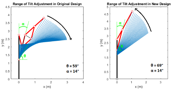
For both original and new designs, once they have reached their default open states, their tilt angles θ can further be increased, resulting in height changes. The max tilt adjustment is bound by additional physical properties of the links and mechanisms such as width that are beyond the scope of our analysis. Instead, this is defined based on a condition of the smallest angle between the links, α = 14°. The reasoning is that the original design constraints its max tilt at this condition, which is found through calculations based on the minimum slider height of existing designs on the market.
For a constant α = 14°, the final proposed design can reach a maximum tilt angle of 69° vs the 59° of the current design: a 10° increase. When increasing the tilt angle, the span of the canopy increases its height in the final proposed design, while it decreases in the current design. This occurs for the entirety of the tilt adjustment process regardless of angle, which allows more space for users underneath the umbrella; however, the higher height may also remove the user from coverage when operating the hand-crank at the pole. The drawback is that the minimum tilt angle cannot go as low as that in the original design, which we consider a valid tradeoff.
(a) Current Design: 5° < θ < 59° (b) Final Proposed Design: 36° < θ < 69°
Conclusion
The table below summarizes how the final proposed design compared to the current design. Overall, it was a successful design for the users.
Summary of Current Design VS Final Proposed Design


